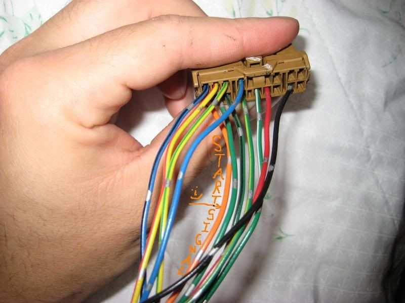
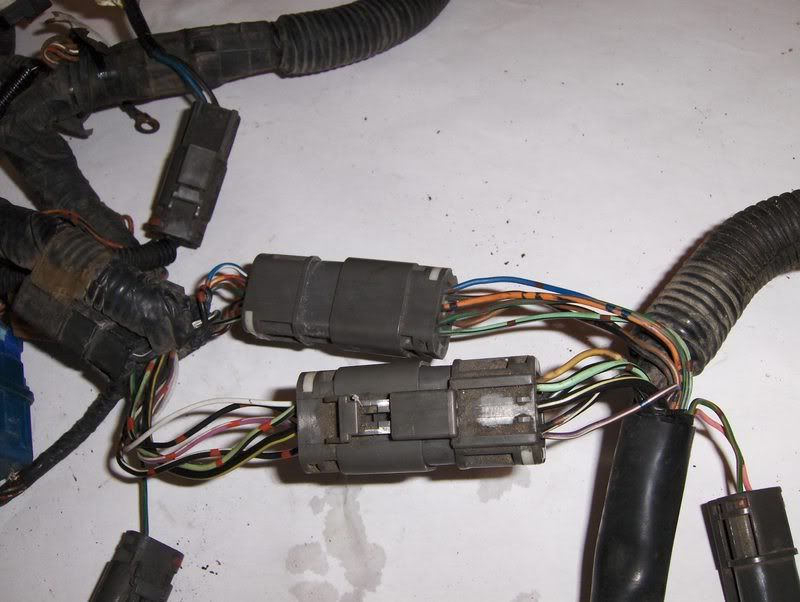
TO CONNECT UP YOUR FUEL PUMP CIRCUIT: NOTE THIS INFORMATION IS NOT ON THE DIAGRAM ABOVE.
First off, I need to explain how the fuel pump circuit functions. It is critical you understand this before modifying the system.

The fuel pump circuit is ground-side controlled. What this means is that power is supplied to the fuel pump, and either the computer-- or the fuel pump relay-- controls the ground, and therefore whether the pump runs or not.
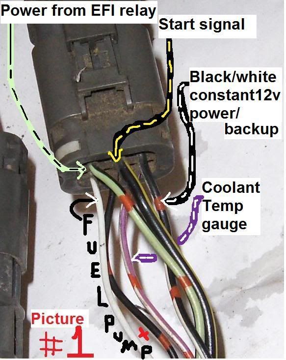
So in the S12, when the key is turned to the ON position, 12V power is supplied through the fuse block back to the fuel pump through a BLACK/RED wire. On the ground side of the fuel pump, a black or white wire exists (depending on when your car was built, how stoned the guy was building the loom, the position of Neptune, who the fuck knows). This black wire or white wire runs through one of the connectors in the engine bay (PICTURE #1), back up to the computer, and then the computer grounds the wire as it sees fit, turning the pump on or off (or somewhere in between, actually).
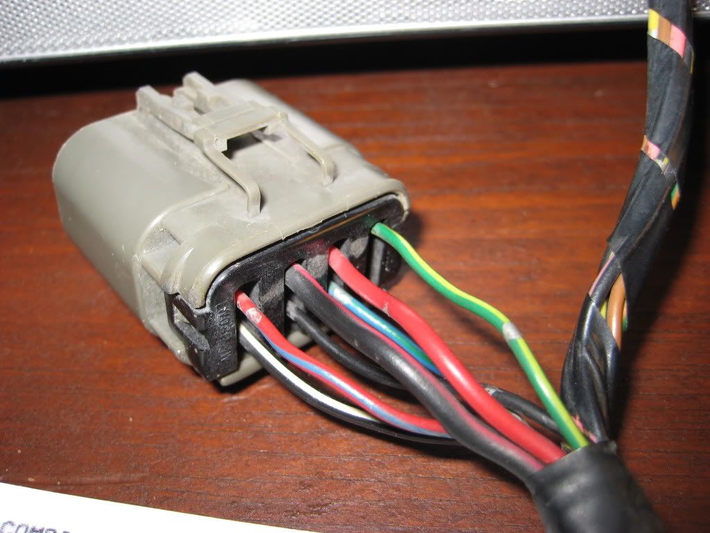
The other wire that you see, the one that's located in the middle of the connector, is the shielding wire. When current flows through a wire, it creates a magnetic field, which can disturb the flow of electricity in other wires that are near it. So Nissan took bare metal (in this case, aluminum) and ran a stranded cover overtop the rubber insulation of the fuel pump wires.

When it gets to connectors, though, the metal covering has to split off, so they put it through an extra pin in the connector. This covering is normally grounded at one end, in the case of the S12, it is normally grounded through the CA20 EFI harness on the engine somewhere, which you just removed. So what I do is either splice in a wire to that black-with-red-dots wire in PICTURE #1 and connect the longer wire to ground, or just connect that original one directly to ground with a screw, its whatever you like.
end of lesson.
--------------------------------------
SO…
For the fuel pump control, there are several options.
IF you are using the stock pump,
1. You can directly hard-wire the pump to ground which means that it will run all the time when the key is on. Normally the pump is controlled by the ECU, either directly or through a relay, and will only run for a few seconds before and after startup. If you hardwire the pump direct, you will bypass this function. Benefits are simpler wiring; drawbacks are potential hazard in an accident (normally if the engine would stop running, then so will the fuel pump). That decision is yours to make.
There are several ways to hardwire the pump directly, you can choose to ground it out either somewhere near the rear of the car- by the pump, by the connector- or you can ground it out in the engine bay where the EFI connectors are at. Again, this is preference. As long as you are modifying the wires up front, I'd rather do it there, as its less work and less chance of a spark near the rear of the car if things came undone.
If you decide to ground the wire at the connector in the engine bay, you will need to ground the wire that is located on the outside corner of the connector. I have run into different situations as to what color this wire is, IN this picture it is represented by the WHITE wire in PICTURE #1. You simply ground this wire to a good, clean, secure ground.
If you decide to ground the wire in the rear of the car, you will need to look at the fuel pump connector. The wire you are after is located on the *OPPOSITE* end of the connector with the BLACK/RED wire. See picture.
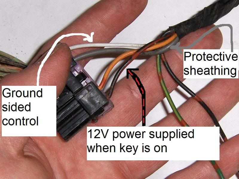
Sometimes this wire is black, sometimes its white. It should match whichever color the wire is up front in the engine compartment as shown in PICTURE #1. Ground this wire, and then the pump will run all the time when the key is on.
...........
2. You can add in a relay control. Since the computer we are using here is an S13, you can take a look at the lower diagram.
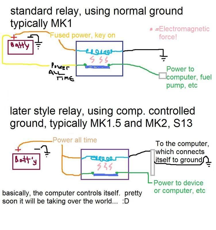
^The lower diagram is the system that needs to be set up.

What can be done is this. Take the WHITE -or- BLACK wire,(... depending on which you have, in PICTURE #1 on the outside corner of the connector...,) that is going to serve as the one of the Switched leads. Connect the other switched side to a GROUND of your choice, however you want to do that.
For the Control side of the circuit, tap the constant 12V BLACK/WHITE wire in the S12 Connector in Pic#1 and connect it to one of the control side leads. Now take the other control side of your relay and connect it to the S13 BLACK/PINK wire.
JUST MAKE SURE that you do NOT send the solid 12V to the BLACK/PINK wire. This will damage the ECU. The BLACK/PINK wire MUST be connected to the control side of the relay ONLY.
-----------------------------
IF you are using an aftermarket fuel pump, like the high-flow Walbros, you're going to need to run a larger power supply wire than the factory one. Once that is done, you can connect in a relay in similar fashion, its just the setup of the wires that will be different.
You are adding the NEW RED wire. It could be blue, green, pink, whatever. I used RED for this example.

What is necessary here is changing the arrangement of the wires at the fuel pump connector. You will need to cut the WHITE wire (or BLACK wire depending on your setup) from the connector, because that is going to be the relay control circuit, and you don't want a full 12 volts going thru back to the computer as I mentioned before. That WHITE (or BLACK) wire, the section that is left connected to the actual pump CAGE/SENDING UNIT, needs to be connected to ground now, wherever you decide is a good clean place to ground to. The other section of the white wire, which goes to the front of the car and is now not connected to anything, is going to get connected to the relay and serve as the control side of the relay.

A closer shot,

NOW for the BLACK/RED wire, you are going to be extending the Connector end of your cut wire to the relay, where the relay when activated will provide 12V to the fuel pump itself.
THE OTHER END of the BLACK/RED wire, the chassis side of your cut, just needs to get capped off. Do this well otherwise you'll be blowing fuses, etc, if it shorts to ground, because that circuit will still be sending power thru that wire. I don't think you can just pull the fuse, as that same BLACK/RED wire also sends power to the ECU. You could use to power something else back there I suppose, but the OEM pump only pulled 2amps down that circuit, so it better be pretty light if you do add anything.
NOW for the OTHER end of the chassis white wire, up front in the connector in PICTURE #1, you will connect this to the S13 BLACK/PINK wire. Again, this is happening at the front of the car, in the engine bay.