Browse › Engines ›VG30E

MK1 Swap guide CA20->VG30!

Started by 200sxkitcar · Nov 18, 2010 · 9postsSMF 2010–26

200sxkitcarNov 18, 2010, 7:42 pm · #1
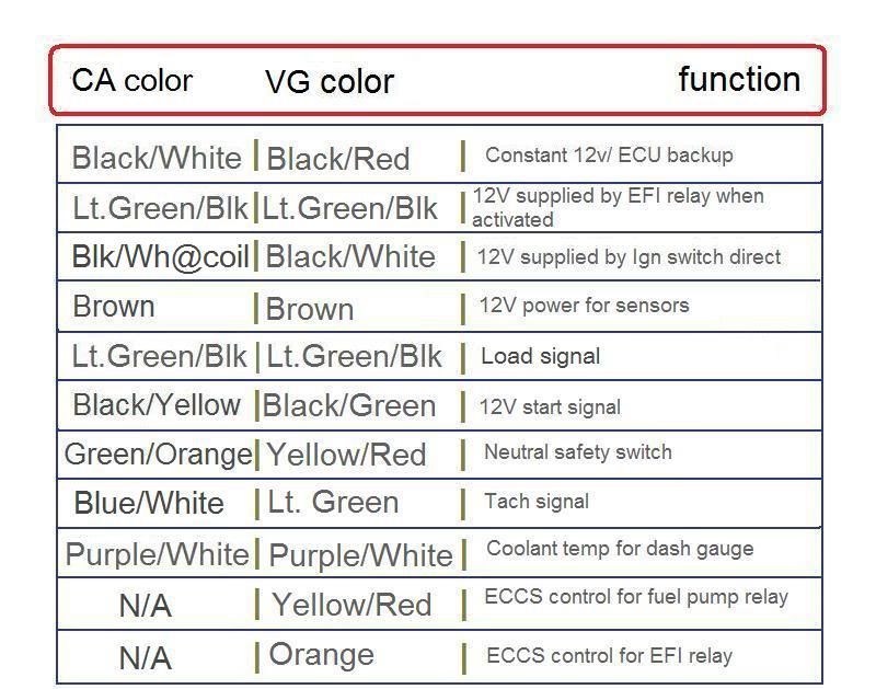
posted image

Follow the pictures closely, as some wires repeat color thru the different connectors.  READ.
Print this shit out, it will be much easier to follow.

VG CONNECTORS
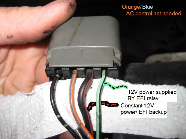
posted image
posted image
posted image
posted image
posted image
posted image

MK1 CA20 CONNECTORS
posted image
posted image

NOTES

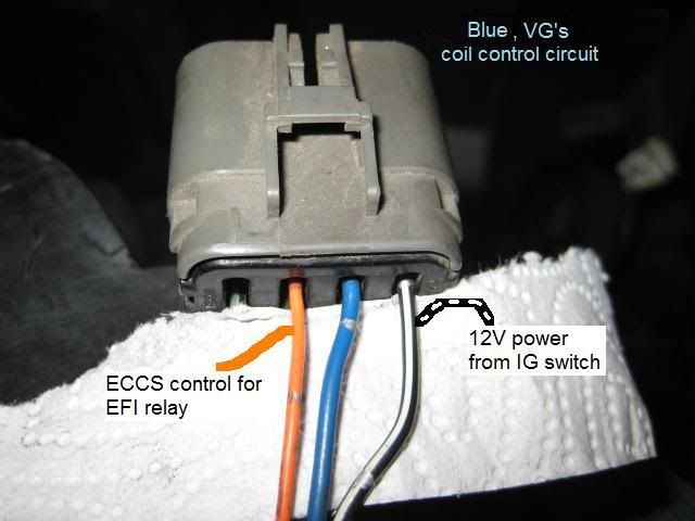
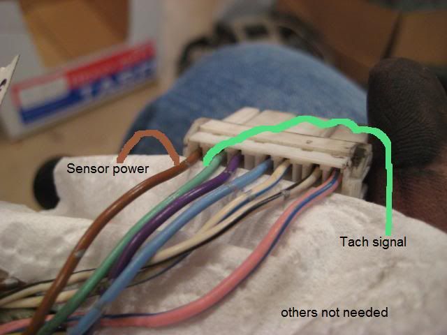
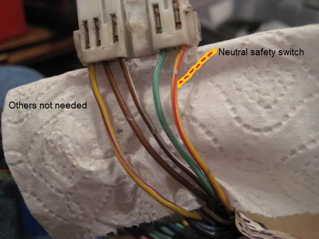
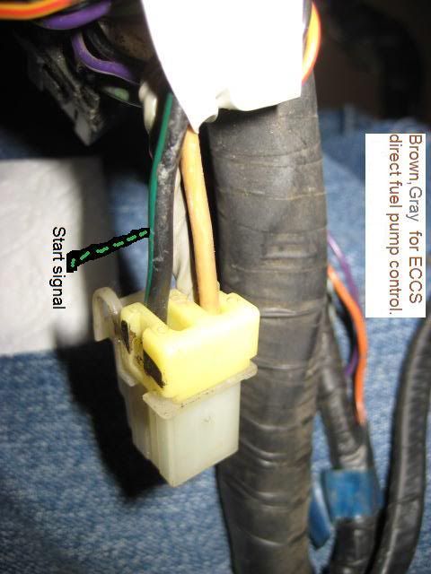
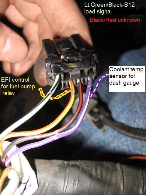
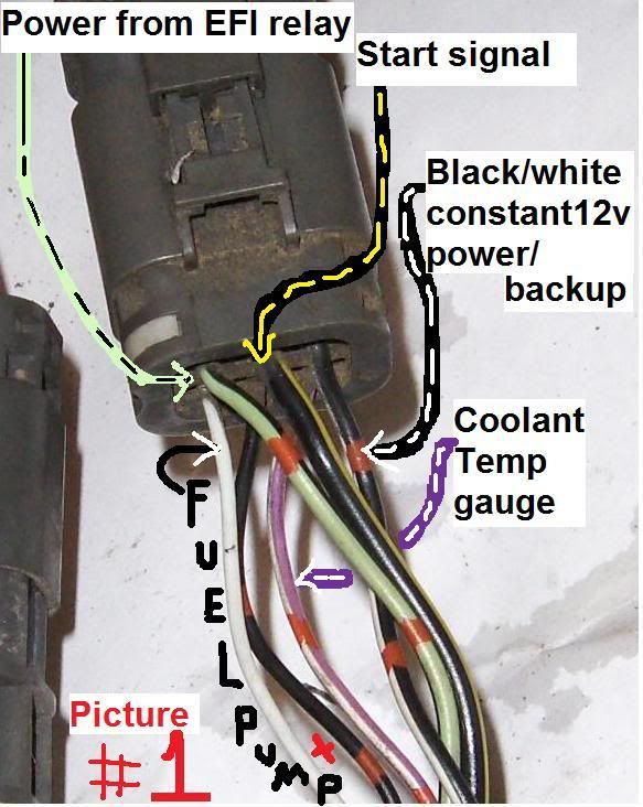
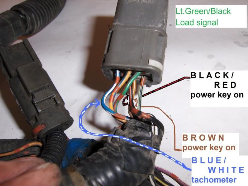
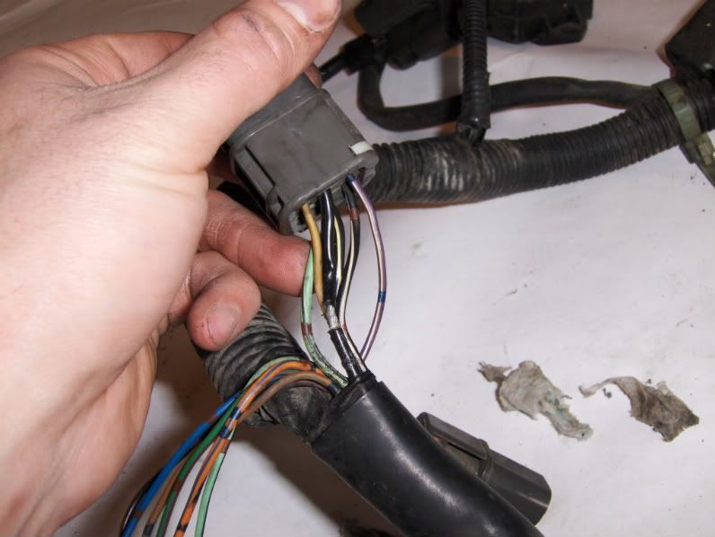
These connectors will be found where the CHASSIS harness connects to the ENGINE harness.  Through these connectors, the ECU gets its power and communicates with the chassis.

The best thing to do is cut a chunk of the VG  CHASSIS  harness that plugs into the coil and reuse it.  If you unwrap the wiring harness between the main 8 pin connector and the coil harness some of it is directly connected.  If you can reuse it, great, its that much easier.

The EFI relay is controlled by the CHASSIS harness in MK1 CA20's so don't worry about its function, it is independent of the motor.

Fuel pump direct control can be reused, but an override fuel pump relay does not exist on MK1 CA20 cars.  You can add one, or figure a way you desire for the fuel pump to run anytime the key is on.  Realize in an accident the pump will continue to run, hence the factory's computer control.

The three wires for the VG ALTERNATOR (two fat white wires, they are the same, and one white/red wire for the charge light on the dash) will need to be stretched from the passenger's side (on four cylinder cars) to the driver's side.  Match the wire thicknesses and colors, it would be easy and decently safe to run the wires along the VG's power steering lines down low.

The note 'BLK/WT@COIL' means you will need to use one of the BLACK/WHITE wires that fed the CA20 coils.  It does not matter which coil, the intake one under the airbox is handy as the VG coil should bolt down right there easy.  This wire is NOT in the two six pin MK1 CA20  CHASSIS  harness.  Make sure any leftover connectors (IE the other coil plugs etc) are isolated and wrapped/tucked where they cannot short or rub on anything.
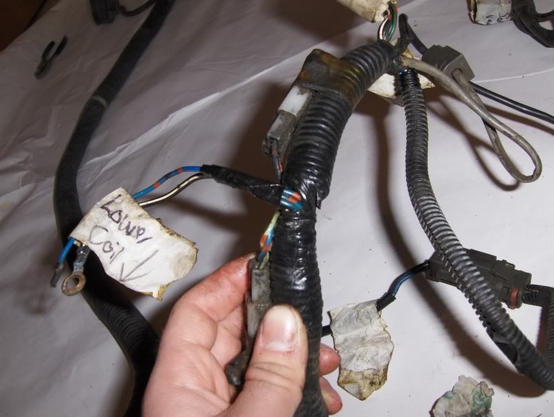
posted image

TRANS/LOWER HARNESS

It would be easiest to use the VG's manual trans harness as it is.  Just splice the four wires that are in the VG lower harness to the MK1 CHASSIS harness or connector- the colors are the same-
GREEN- 12v power to reverse light switch
GREEN/YELLOW- 12v from reverse light switch TO reverse lights
GREEN/ORANGE- neutral safety switch
BLACK- needs to be grounded.  Does not need to connect to CHASSIS harness at all.
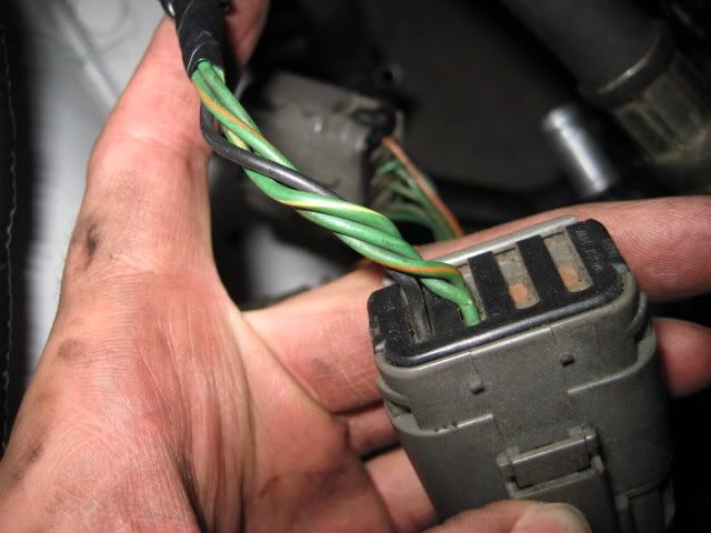
posted image
VG lower harness.

IF THE CAR WAS A MK1 AUTOMATIC CA20E
The automatic trans harness is simply the manual trans harness with a different connector for neutral safety/reverse switches (they are all in one in the range switch) and an ADDITIONAL harness wrapped in.  If you unloom the auto trans lower harness and separate out the wiring that is auto-trans only (it will be obvious) and cut/splice or add connectors to replace the single 4 pin connector to go to two separate plugs (that is what the manual trans has) you'll be set.
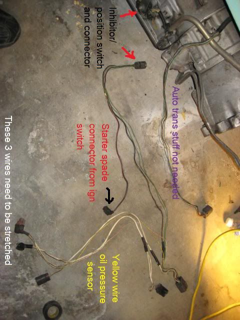
posted image
SlickS12Nov 19, 2010, 12:19 am · #2

Thanks to you sir for such a detailed write-up!  This is going to make things a lot smoother tomorrow when all this gets wrapped up.  It all seems fairly straight-forward with very little/no guess work, just a little patience when de-looming everything.

The technical, electrical professor has struck again!  WTG Ling Ling

200sxkitcarNov 19, 2010, 1:04 am · #3

lolsauce!

hit me up if youve got questions that arise.

likely be down for some of the weekend...

SlickS12Nov 19, 2010, 2:56 am · #4

Im wondering if it makes any difference if I stripped the black/white stripe wires from the ca coils to where they all met commonly in the harness i.e. where three wires met from a common source, if that would be a good place to connect the other black/white stripe wire from the vg harness.

EightySix200SXNov 19, 2010, 7:30 am · #5

Sterling is a FUCKING MONSTER!!! he eats this shit for breakfast mayne.
Nice work sterling +1 sticky this nice bit of info!

200sxkitcarNov 19, 2010, 3:25 pm · #6

lol Justen!

actually I need the pics from your KA swap, Im trying to finish that swap thread.

DETAIL OF SHIELDED WIRING FOR FUEL PUMP
reference pic
posted image

you can see how the outer wrapped shield condenses together and runs into the connector, on the other side of the connector it may rejoin in one shielded wire.

Stretch these two wires (either as one in a shielded wire or individual) along with the S12 CHASSIS BLACK/RED 12v+ wire   TO   under the dash where the other VG connectors are.  Connect to VG's shielded wire arrangement in the same manner as factory at the connector under the dash, a relay is added here as well.

(diagram for relay install)

SlickS12Mar 31, 2011, 7:17 pm · #7

Im slowly starting to think there might be a problem with the current wiring setup, not the one detailed here, the way I wired it...

What would cause the car to run fairly decent but as soon as the O2 sensor is plugged in it runs like dirt.  Thats with a NEW O2 sensor =\

MaxpowMar 31, 2011, 8:20 pm · #8
SlickS12 on 07:17:01 PM / 31-Mar-11
Im slowly starting to think there might be a problem with the current wiring setup, not the one detailed here, the way I wired it...

What would cause the car to run fairly decent but as soon as the O2 sensor is plugged in it runs like dirt.  Thats with a NEW O2 sensor =\

Dude you are a douche. Its the fucking wire that your ECU is missing for imput regarding the mass air fuel readings. C'mon man. Fix that.
Colonel GustardMar 31, 2011, 9:10 pm · #9
Maxpow on 08:20:38 PM / 31-Mar-11
Dude you are a douche. Its the fucking wire that your ECU is missing for imput regarding the mass air fuel readings. C'mon man. Fix that.
+1