Browse › Tech ›Brakes, suspension and wheels

Adjustable control arm conversions by RT

Started by G-E · May 22, 2014 · 60postsSMF 2010–26

G-EMay 22, 2014, 12:18 am · #1

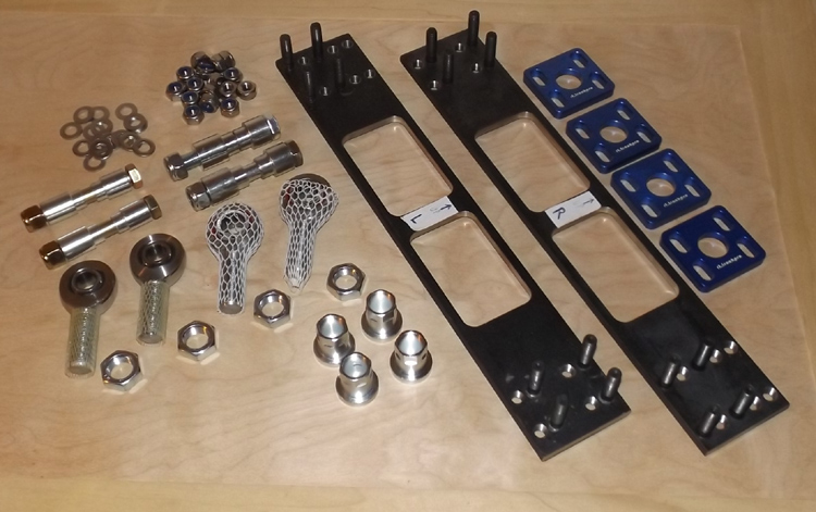
The trailing arm rodend conversion kit will be ready for consumption the first week of june if all goes well... price TBD

Each pivot will be able to adjust 2cm in length and slide up/down for a total of 1cm movement, the subframe tabs can be slotted vertically for rollcenter adjustment :)
(http://responsetype.com/imagedump/trailing-arm-conversion-kit.jpg)
(http://responsetype.com/imagedump/clamp-plate.jpg)

And not to forget the front, a more universal conversion kit will be available at the same time (should work with s13 arms as well)

Still waiting on the double threaded adjuster sleeves to arrive...
(http://responsetype.com/imagedump/flca-bungs0.jpg)
(http://responsetype.com/imagedump/flca-bungs1.jpg)
(http://responsetype.com/imagedump/flca-bungs2.jpg)

BasicMay 22, 2014, 8:01 am · #2

interesting concept - I have been looking at the S/A inner arm adjustment kit but I like this as well. What's involved in install? I assume that plate gets welded back to the subframe and the rod ends take the place of the bushings on the trailing arm?

G-EMay 22, 2014, 8:37 pm · #3

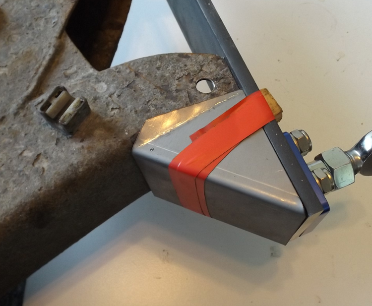
Welded...

(http://responsetype.com/imagedump/flca-bungs3.jpg)
(http://responsetype.com/imagedump/flca-bungs4.jpg)

DjayS12May 23, 2014, 8:23 am · #4

Basic: I believe you weld the big bar on the trailing arms and you then bolt the plates with the rod ends on it. Moving the plates up and down change the camber/roll center and bolting in and out the rod end adjust the toe.

Any idea when these will be available? If fast enough, I might buy them instead of making my own to save some times. Both the rear and front setup.

G-EMay 23, 2014, 12:59 pm · #5

Djay you are correct, you can always weld the whole plate at an angle to already move everything somewhat, and you can slot the tabs on the subframe vertically for more adjustment...

Yea I am behind on a couple of small components, but I should have everything ready first week of june...

I may offer a plate with multiple stud positions as a second revision later, to make life easier for the super slammed :)

DjayS12May 23, 2014, 1:30 pm · #6

Will the rod ends be included? Or it's the buyer to buy is own rod ends?

G-EMay 23, 2014, 7:56 pm · #7

Depends on pricing I get, but that's the plan...

G-EMay 29, 2014, 1:50 pm · #8

So I have almost everything nailed down for costs...  I am just working with a new revision of the backing plate for the rears

Installation will be very very simple, as it requires a straight cut, and some welding... if you're good with a tape measure, a square, a sawzall, and a handfile, you can do all the prep work for someone else to do the welding

The FRONT kit will be $170-180+ship

The double adjusters should allow >1" of safe length adjustment, the recommended install is to split the difference, allowing for longer and shorter total length

Keep in mind the tension rod holes will have to be slotted in the opposite direction of the length adjustment to avoid binding

_____________________________

The REAR kit will be $280-300+ship

The rear kit should allow >3* of camber correction using alternative stud positions for coarse adjustment, fine tuned with the slotted plates from there

The outer plate will be installed to slide horizontally, the inner plate to slide vertically, track width adjustment will be possible with flipping the rodend spacers around, and/or cutting the spacers, then using washer stacks to take up the difference where needed

Toe and wheel position will be adjustable by extending the rodends from the turnbuckles, each side should allow 20mm of safe extension from it's fully wound in position... again when measuring to cut, bias your cut to allow maximum travel in the direction you want, or split the difference, using a combination of extending and retracting the two pivots

** rodends and some other hardware is arriving early next week, once I have a final decision on the backing plate design, I will have 20 made, should take about a week from there

DjayS12May 29, 2014, 2:13 pm · #9

As soon you have a front and rear set ready for shipment let me know. I have PayPal ready and i'm willing to take pictures of the install and provide feedback.

D-sport S12May 29, 2014, 7:37 pm · #10

In for rear kit

G-EMay 30, 2014, 6:05 pm · #11

Current backing plate design:

(http://i.imgur.com/sWDBYsr.jpg)

Should help stiffen the whole trailing arm if you leave the braces connected, otherwise it can be cut out to save weight

G-EJun 2, 2014, 5:02 pm · #12

All the studs and nuts and things arrived... still no rodend hardware blah... I hate waiting

DjayS12Jun 3, 2014, 1:18 pm · #13

Getting there! I hate waiting after you waiting for bits but hey what can i do!

Keep us updated.

G-EJun 10, 2014, 12:55 am · #14

Assembled with backing plate...  the studs I sourced are too long, but I don't have much choice besides ordering specialty studs through a specialty supplier at triple the cost...  cutting is free though!

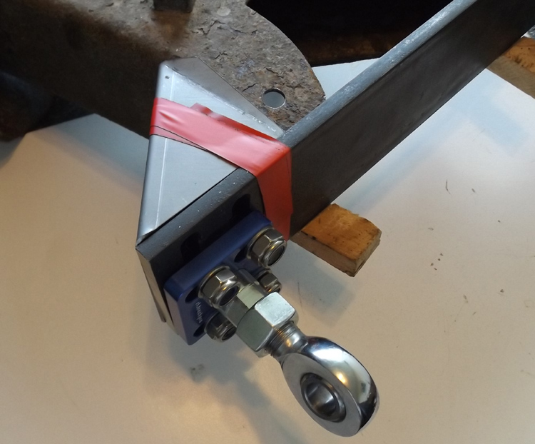
So if you see each side has several positions for the adjuster plate, this is because the same plate is used for left and right side installation, the location of the studs is what determines which is which... this leaves 3 possible base positions for camber, 1 for more negative, 2 for more positive, the adjusters then move the camber positive or negative from there.

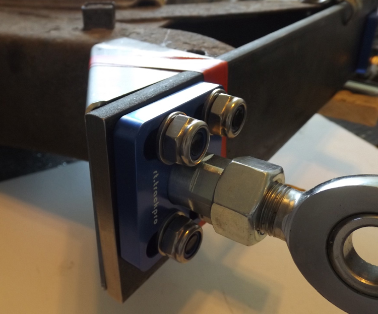
The clamping plates are held by locknuts and washers, the plates will move with as little as 1/4 turn of the nuts, 1/2 turn would be fully loose, and because the turnbuckle has a flange that overlaps the nut area, there is little risk of misaligning the plate.

(http://responsetype.com/imagedump/backing-plate-assembled.jpg)
(http://responsetype.com/imagedump/camber-adjuster1.jpg)
(http://responsetype.com/imagedump/camber-adjuster2.jpg)

DjayS12Jun 10, 2014, 5:15 am · #15

Pretty! I just notice that the bolted plates don't sit agains the backing plates.. I guess it is from the rod adjuster that stick out past the plate a little bit so it won't be like that once installed?

*EDIT* Just re-read the last post properly. So the blue plate just clamp the  adjuster agains the backing plate so it is meant that way. Any idea of the torque that should be applied to the nuts to make sure it doesn't slide on the slots?

I really dig that kit! Best way to get rid of bushing binding and camber issue at the same time.

D-sport S12Jun 10, 2014, 3:16 pm · #16

So stoked on this

G-EJun 10, 2014, 4:09 pm · #17
DjayS12Pretty! I just notice that the bolted plates don't sit agains the backing plates.. I guess it is from the rod adjuster that stick out past the plate a little bit so it won't be like that once installed?
Yea the clamping plate pushes entirely on the turnbuckle, the plate has a recess so all the clamping force is applied to the turnbuckle, this also means that there's room to tack weld the studs; better still, wear will not cause a loss of clamping ability by bottoming out, ever :)

DjayS12*EDIT* Just re-read the last post properly. So the blue plate just clamp the  adjuster agains the backing plate so it is meant that way. Any idea of the torque that should be applied to the nuts to make sure it doesn't slide on the slots?
Very little force required, you can go from full tight to loose enough to tap with a mallet in 1/4 turn, I'd say 25-30ft-lbs is all they need... they should be tightened in sequence like a wheel, but if you just go in stages it will probably be fine (you'd have to crank one really tight before touching the others to misalign the plate)

PS. the plate is 10mm aluminum, both the tolerance to the turnbuckle and distance to the studs are small, there's no chance of deflection within those distances

DjayS12Jun 10, 2014, 6:57 pm · #18

So pretty much everything is ready except for the rod ends that you are waiting for?

G-EJun 11, 2014, 4:57 am · #19

(http://responsetype.com/imagedump/backing-plate-assembled.jpg)
(http://responsetype.com/imagedump/backing-plate-mockup1.jpg)
(http://responsetype.com/imagedump/backing-plate-mockup2.jpg)

D-sport S12Jun 11, 2014, 7:21 pm · #20

So happy about this, can't say it enough.
When do you figure these will be ready for sale?

G-EJun 12, 2014, 12:29 am · #21

I need undercar pics of the area to see how much room there is to offset the arms, the upper surface of the arm would be able level with the upper edge of that backing plate you see...

I need to know if the arm is going to hit the body at compression (or any other interference issues), and devise the easiest instructions to do the modification... that way I can help anyone interested offer a welding service to end users without fab ability

I am also speaking a pro in auto-x (z31) who knows his stuff, he eagerly wants to try it, and he's the ideal person to go about testing all the various geometry changes and settings for me

First step is I need lotsa underbelly pics of the s12 around the subframe area, please anyone/everyone get me pics! :)

G-EJun 17, 2014, 7:26 pm · #22

Lotsa interest, zero effort...

I don't think you guys want this badly enough :\

D-sport S12Jun 17, 2014, 10:24 pm · #23

I won't be home till Thursday to get pictures. I said that on Facebook as well lol, cause I'm stoked on this. Would be nice to have some more grip + even tire wear for drifting

G-EJun 18, 2014, 12:49 am · #24

I'm having more backing plates made, going to be sending the first prototypes to a z31 tester probably end of next week

If any of you feel adventurous enough, I can let someone else be a dedicated s12 tester? Not much discount, but exclusivity and handjobs from engineers could be yours...

Mr Amber ShadesJun 18, 2014, 7:40 pm · #25

handjobs from engineers you say?.... lol couldn't resist

I'm stoked about this.  Current lack of rear adjustment kills me

D-sport S12Jun 18, 2014, 8:25 pm · #26
G-E on 12:49:57 AM / 18-Jun-14
I'm having more backing plates made, going to be sending the first prototypes to a z31 tester probably end of next week

If any of you feel adventurous enough, I can let someone else be a dedicated s12 tester? Not much discount, but exclusivity and handjobs from engineers could be yours...


In for this, I'll drift stress test it with enough power to actually test it a little.... Around 300rwhp
DjayS12Jun 18, 2014, 11:06 pm · #27

Totally interested, as I said i'm on a ship until the 22nd. As soon I'm off the boat i'll take these pictures if nobody have yet.

Also interested in testing it, we got a new track locally and I lapped the car with only coilovers and urethane bushing. I know I wanna go lower and get rid of the bushing binding. This kit is the best solution for now from what I believe!

G-EJun 22, 2014, 5:40 pm · #28

How much camber are you guys trying to undo? I have 2 plates with studs installed in the maximum positive positions, although with the sliding plates you can go more negative from there...

I need some alternative rodends to arrive before I hand out the second tester kit, but expect a week or so for that...

seishukuJun 22, 2014, 7:18 pm · #29

This much?
posted image

Probably a good 8 degrees.

G-EJun 23, 2014, 4:12 am · #30

Haha that doesn't look like 8 but definitely high... 

Using simple math, my trailing arm kit would allow 4.1 degrees of tilt, but since the arm isn't trailing exactly straight back, realistically it's more like 3.5-3.8 degrees of correction

Anything above that would require a more expensive solution

pakii-afaJun 23, 2014, 12:45 pm · #31

yea im already running like -5 degrees on stock everything lowered 2 inches. looks just like seishuku's car almost.

one thing that would be done is instead of welding the plate on square, weld it on a more positive angle for more adjustment.

G-EJun 24, 2014, 12:42 am · #32

This is true, but the plate itself is just about the exact height as the arms where they get cut... it's like that so you can use the top edge of the arm as a vertical guide, then you only need to measure the horizontal position and the cut line offset from the ends

I wanted installation to be as simple as possible :)

The biggest challenge with welding the bracket at angles, either forward/rearward tilt, or rotation, is you likely need to make up a jig to keep both sides consistent, something I wanted to avoid the need for...

DjayS12Jun 24, 2014, 1:18 am · #33

Ok I'll take your pictures tomorrow. I gave it a quick look and I think we will have to cut out the middle portion of the plate because the frame rail goes between the two arm legs if you go somewhat low (or hit a bump). The inside leg seem to have plenty of room to jack the arm tho!

pakii-afaJun 24, 2014, 1:24 am · #34

i understand that, but what if one was to cut a side, and since the arm is not boxed, bend the arm into trapezoid fashion, tac weld. mark the other side for cutting. cut, bend other side to match trapezoid. then weld in full. i feel as if ive over looked something like potentially "fouling/warping/binding" the arm itself by doing this. but its just a theory.

maybe just cut, weld the arm into a boxed form. then weld the camber plate onto the desired angle?
i tend to make things over complicated.

G-EJun 24, 2014, 3:20 am · #35

Not sure what you're describing exactly, but adding extra material that close to the pivots will affect unsprung weight by about 1/4 of what you actually add, therefore an extra kg of steel won't really make much difference...

I'm going to leave the gusseting and boxing to the installer, like my subframe swap kit, I'm trying to provide the components you can't just make from scrap metal with a grinder

I did expect the cross bracing might have to be cut (possibly the same for the z31 guys), and I may still be able to redesign the plate to clear, but I need to know what/where/how first :)

On the plus side, you won't need to relocate the brake hard line, and if you're careful cutting, you could even keep the the bracket that comes off the arm...

pakii-afaJun 24, 2014, 3:57 pm · #36

yea i tend to over complicate many things, sorry about that lol

G-EJul 3, 2014, 11:54 pm · #37

Ok I just have to get 2 spacers trimmed up and I have another set ready for testing by one adventurous s12 owner...

Price will be $360 shipped, and I will help walk you through the install, answer the million questions, offer advice, send love letters etc.

The other criterion is that you actually install it asap, I need to know if there's any tweaking or s12-specific trickery; first to verify that no changes need to be made, and secondly so I can work on some proper documentation/diagrams
Post Merge


Sold to lucky contestant #2...  ;)
ProlowtoneJul 5, 2014, 5:15 am · #38

how much would need to be cut off of the rear arms. Im actually a lil bit stoked  :thumbsup:

Just noticed page two is the testing phase. I have all my photos on my desktop and have been away for almost a year and disappointingly noticing i dont have any upskirts of my 12s despite having a lift in my garage hahahaha.

G-EJul 5, 2014, 10:24 pm · #39

Cut line is 4.5" or so from the very end of the arms, measuring from the center of the bore would just complicate things... BUT if you want longer arms, you could cut less, and if you wanted a wider track, you could weld the plates offset more, which would then need extra length

pakii-afaJul 6, 2014, 1:34 am · #40

wouldnt having a wider track via offset arm require custom axles?

G-EJul 6, 2014, 2:23 am · #41
pakii-afa on 01:34:33 AM / 06-Jul-14wouldnt having a wider track via offset arm require custom axles?

Axle spacers are easy to make, but that all depends how much you offset it right

Now it's possible the 240sx 3x2 spacers would work on the s12 and z31 non-turbo axle stubs, but I've never tried, AND it's possible to use 87+ z31 inner axle flanges which are deeper, I'd like to say by 10mm...
ProlowtoneJul 6, 2014, 2:31 pm · #42

good idea.. Now if i had time to implement good ideas. :P pretty sure that i will be buying a pair of rears if they hold up to the on car tests.
Post Merge


They will be added to the parts stockpile for my grey cars ca18det build i have not posted to in over 2 almost 3 years
G-EJul 10, 2014, 1:18 am · #43

So far the kit is looking like this, a ton of parts :)

posted image

D-sport S12Jul 11, 2014, 3:21 pm · #44

Looking good

D-sport S12Sep 8, 2014, 11:28 pm · #45

Bump

DjayS12Sep 8, 2014, 11:38 pm · #46

just thought I would update this, I have purchase a whole bunch of his parts and will install them soon. So far I have the rear control arm conversion, the front conversion, and his set of coilover adapter that I am going to use on some M30 front knuckles.

I'll make sure I make a thread of the steps needed for the install, with comment on how they made the car feel and the new alignment I could get... If everything goes well I will have time to give the car a shake on a lapping day with those before the end of the season.

All I can say is that so far the parts are well done, nicely machined and pretty! I'm curious about how the camber adjustment will work with his coilover adapter, because that would mean that I can use my camber plate as a caster plate and get nice caster (around 7-8 degree) without having the front Wheel pushed forward.

To be continued...

G-ESep 20, 2014, 1:43 am · #47

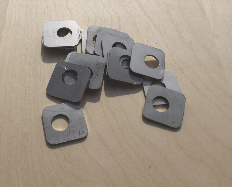
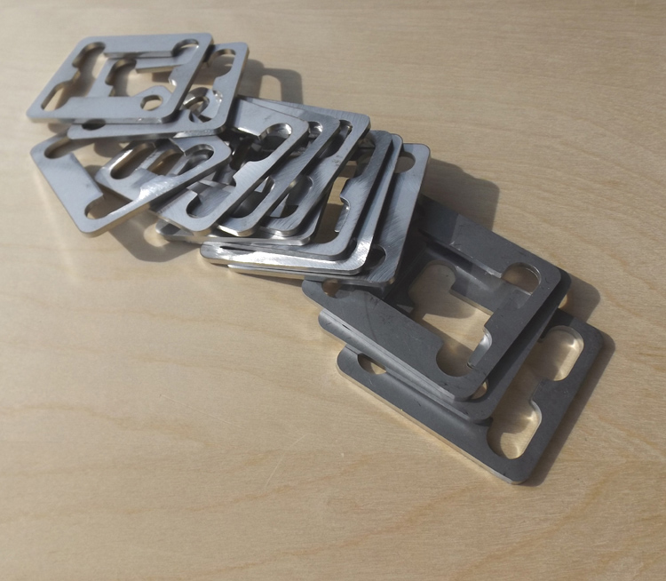
Gussets:
posted image
posted image
posted image

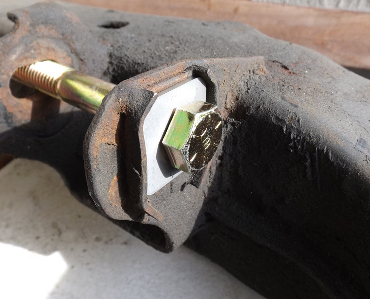
Toe lockouts:
posted image
posted image

Shim plates:
posted image

G-EJan 8, 2015, 4:51 am · #48
posted image

You know that thing you can't do when you slam? Well you can....
D-sport S12Jan 8, 2015, 12:40 pm · #49

I should have some pictures in my build thread end of jan

G-EApr 2, 2015, 6:28 am · #50
posted image

For the first time in 30 over years, the IRS on the Z31 and S12 is no longer an archaic monstrosity to be ashamed of!

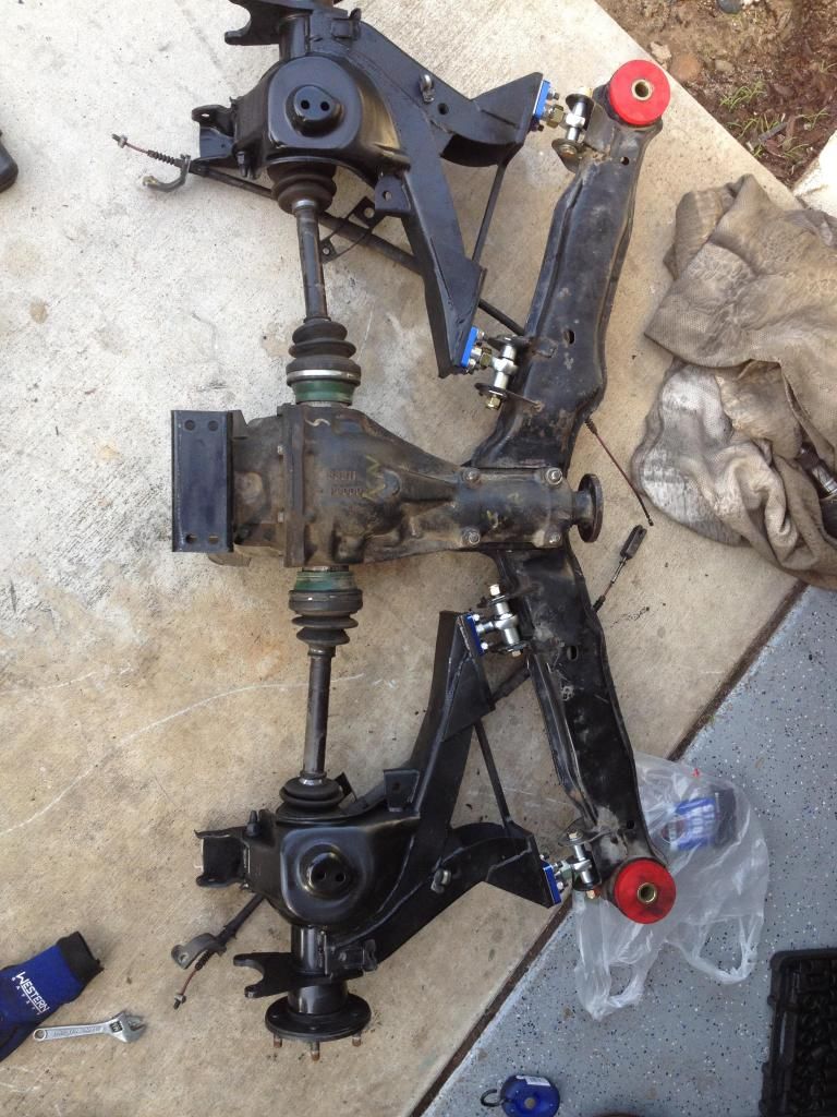
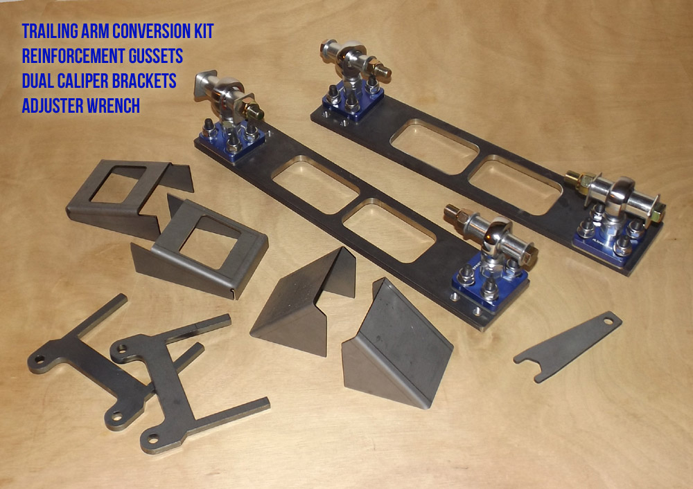
Replacing the bushings ends of the trailing arms with sturdy rodends and adjustment hardware, this kit will allow you to correct your camber fully, correct your toe fully, eliminate the sloppy eccentric bolts that like to seize, and eliminates any possible binding from bushings.

This is not to be confused with merely slotting the subframe, which by it's very nature will not correct camber enough on most lowered cars, and in extreme cases will cause excessive uncorrectable toe. This recipe has been used for years, and has eaten many tires doing so, some people have refused to acknowledge how bad this is, others have accepted it as the price to pay. This no longer has to be the case.

You can have camber and toe within factory specification, even lowered beyond driveable.

The total cost of installing this kit should not exceed $250, and requires no modification to the chassis, the subframe or any other part except the trailing arms.

For more information regarding V1 vs V2 kits, see here: http://z31performance.com/showthread.php?24045-Trailing-arm-mods-thread

Included in the base kit (initial price: $382+ship):
- 2x mounting plates
- 4x turnbuckle adjusters
- 4x clamping hardware with fasteners
- 4x rodends with spacers and jamnuts
- 4x toe lockout washers
- 4x gussets
- 1x adjuster wrench

Limited time BONUS offer (additional $50):
- 2x second caliper weld-on brackets, one for each side

Notes:
This is a limited initial offering, there are 10 sets of V1 and 10 sets of V2 available immediately, and the dual caliper brackets are available as a bundle only until this run is completed. Afterwards, more plates will be made based on the ratio of V1 and V2 demand, and the caliper brackets will be sold as independent items.

A PDF of the modification/installation instructions will be provided...