So over the last year I swapped a LS engine in my S12. I'm not the first one to do it, but as far as I know I'm the first one that made it clean in the sense that the full dash is functional, with a working heater core and without pushing the engine into the firewall.
This swap is WAY more involving than say, a KA24DE swap. But in the end you get a fantastic power to weight ratio, stock engine reliability, loads of torque and power and parts availability everywhere.
So I'll start by listing the parts that I needed and then get in detail of what was done for each part of the build. Please note that some parts could be different (and easier) if you source your engine from a different car than me. Mine came from a 2007 Cadillac CTS-V.
Roughly you will need:
-Engine and transmission combo
-ECM with sensors
-Engine/Transmission mounts
-Custom driveshaft, oil pan and headers
-Upgraded fuel supply
This is the basics to make it run.
Now there are different cars with LS engine that you can use to source your swap. I'll just name the few commons one here with their advantage/disadvantage.
2004-2007 CTS-V
+Better engine accessory clearance, which end up in more room between the engine and radiator.
+Better/tougher synchros on the transmission
-- Transmission is a lot more work to use (read below to see why)
1998-2002 Camaro
+The shifter placement on the transmission is perfect for the swap.
C5 and C6 Corvette
-There is no way to use the corvette transmission
Pontiac GTO
Transmission while not bolt on can have it shifter replaced for a Camaro one to have the correct placement
________________________________________________________________________________________________________________________________________
PART I: Making room for the swap
This part will vary on a few factors (which swap oil pan you used, which transmission variation you have). But here is what happened in my case (CTS-V LS2).
The first thing you have to make room for is the oil pan. You want a front sump oil pan. In my case I had a CXRacing S13 LS1 swap kit coming with the swap when I bought it. The pan is marketed as to fit between the crossmember and sway bar without modifications on the S13. 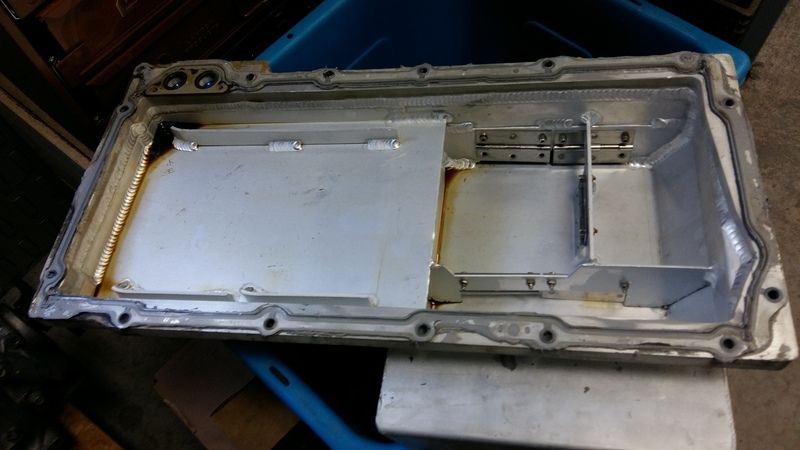
CXRacing oil pan removed, nice piece if you ask me with baffles already in.
This kit is also known in the 240 crowd fpr pushing the engine too far away from the firewall in order to have the pan fit like intended. The engine mount allow you to move the engine back and forth in ½'' increment, but really it is the oil pan to crossmember/sway bar fitment that dictate where the engine will be.
The CXRacing pan barely fit between the crossmember and the front sway bar on the S12. Notice I have a Progress 27mm front sway bar, but it shouldn't change the room available much if at all. The space available was too little for my liking so I notched the crossmember a bit. It also allowed me to move back the engine to a tight distance from the firewall (1/2'' or so).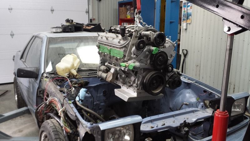
Engine about to be dropped in for the first time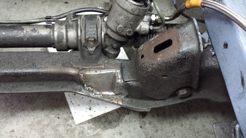
Detail off the notching done to the crossmember. 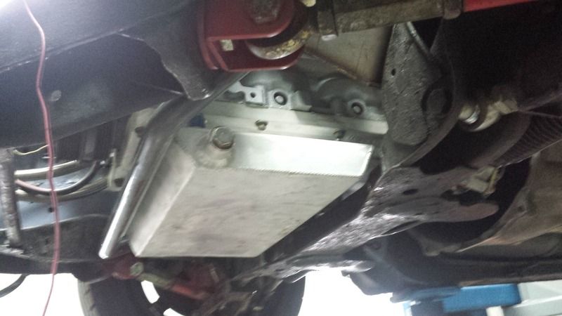
here's how it fit with the notched crossmember. 3/8 - 1/2'' of clearance everywhere.
Now let looks at the transmission tunnel. If you look for similar swap in S13/S14, they can get away with just bashing the transmission tunnel. Well we can't, unless you are okay with having the transmission hanging lower than the frame rails, which is a no no for me!
In my case, I used the T56 from the CTS-V which I wouldn't recommend. It caused a lot of headache. If you can find a T56 from a Camaro it would be much easier. The things that varies from the CTS-V and Camaro T56 are:
-The bellhousing of the CTS-V is a bit longer since the CTS-V use a thicker dual mass flywheel.
-The shifter on the CTS-V is remote of the transmission and much farther back than needed (we will get back on this later).
-The output flange does not plunge in and out. You need to have a driveshaft that can absorb a bit of axial movement, where in most transmission like ours, the output flange slide in and out in the transmission.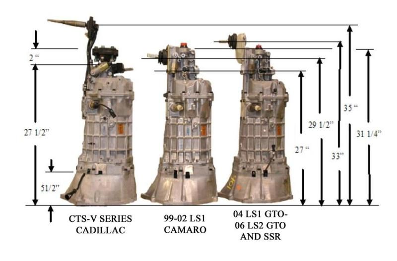
Here you can see how the CTS-V transmission is different.
As I said before, the S13/S14 crowd get away with just bashing their tunnel. I was so far off that I don't even think you could get away without cutting the transmission tunnel like I did, even with the Camaro T56. You might be able just to cut out the forward section with the Camaro. This wasn't an option for me with the remote shifter that lay on top of the transmission.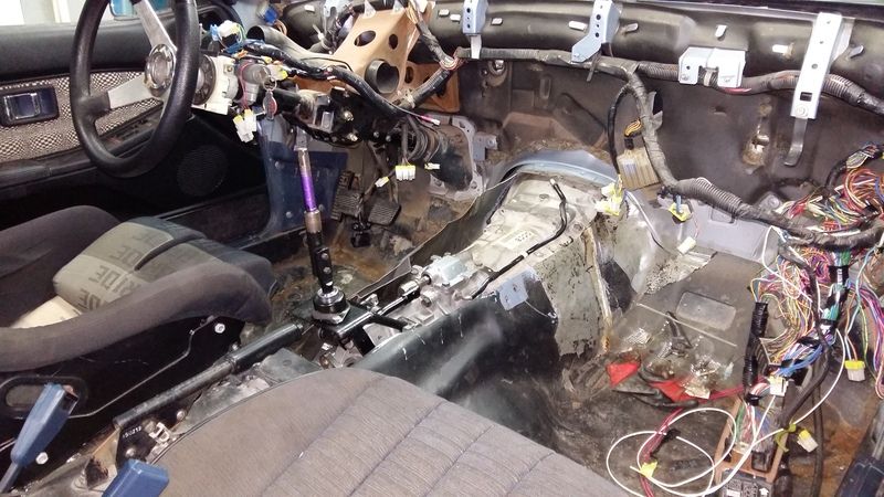
That was heartbreaking but necessary. The top of the transmission tunnel is removed.
On the CTS-V T56 there are a few features that are not needed. One of them is a solenoid that forces you to skip 2nd and 3rd gears to improve the fuel economy in low throttle operation. Good thing because this solenoid was hitting the frame that stiffen the transmission tunnel.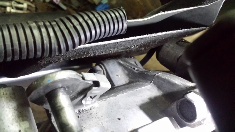
Shifts skip solenoid hitting the side of the transmission tunnel frame. It will be removed and plugged. Notice the frame will still need some hammering to clear on the side.
Before we cap up the tunnel, it is a good time to fabricate the transmission mount. The transmission mount provided with the CXRacing kit was too far off to be used. So I went custom.
I started by cutting the mounting ears on the original transmission mount and tacking some square tubing on them. Then shaped a thick flat bar to hold the transmission at the desired height, then gusseted the flat for added strength. I even extended the left side square tubing to connect to the floor. This additional support through the floor should support most of the moment force on the original mount location since the transmission mount rearward of the body mount.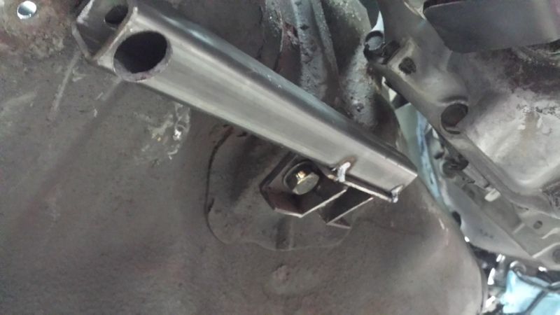
square tubing tacked in place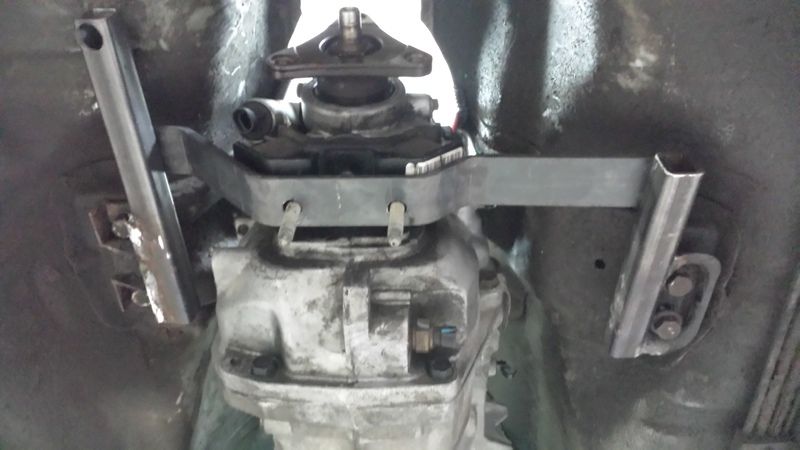
Shaped flatbar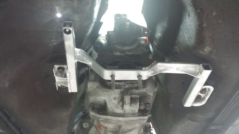
Mount completed
Once the transmission is fixed, I fabricated a new shifter. This part wouldn't be needed with a Camaro T56. 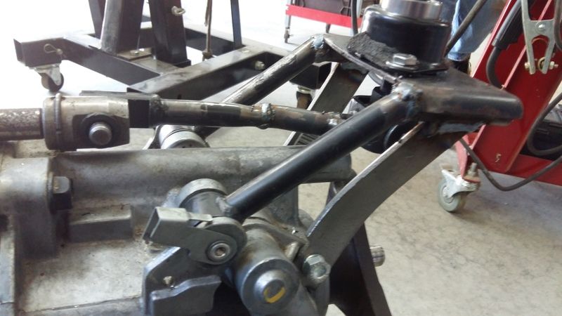
New shifter base that bolt to the transmission instead of the transmission tunnel like it is done on the CTS-V
Shortened the shifter rod to match the new shifter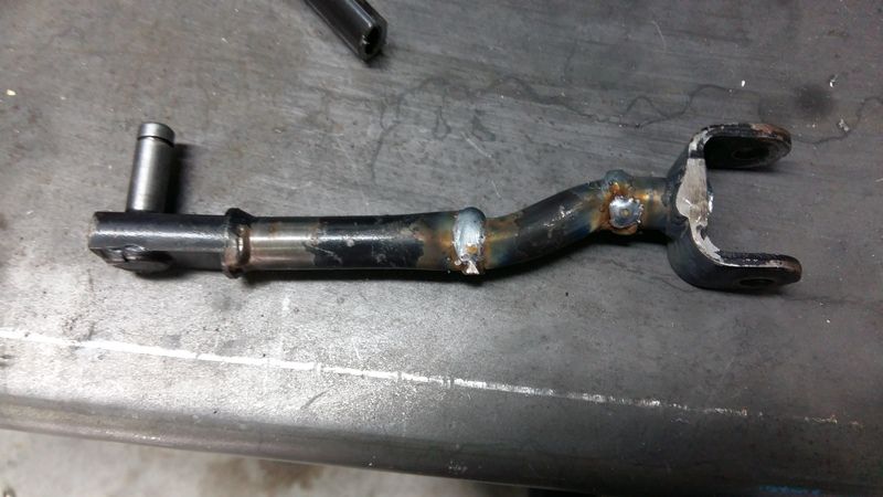
Welded shifter rod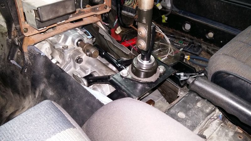
New shifter installed. I upgraded to a Hurst short throw shifter at the same time. Nice short throw and the shifter ball is right by the steering wheel.
Now the next thing to do is to redo the top of the transmission tunnel. I had to modify the metal bracket that holds the dash to the transmission tunnel. The bottom of the bracket would hit the shift box on the transmission.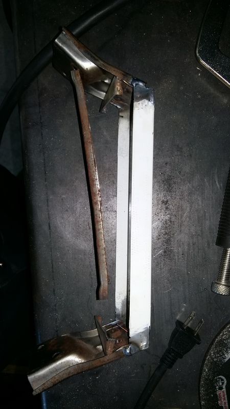
I ended up removing the white piece of metal. But you can still see what part of the bracket I had to remove.
Then I built an extension to the frame that crosses the transmission tunnel. I wanted to make sure that the body wasn't weaker in any way with the modified transmission tunnel. I used some scrap metal that I had laying around from some industrial shelving, then cut and shaped the original frame of the tunnel to match the new frame.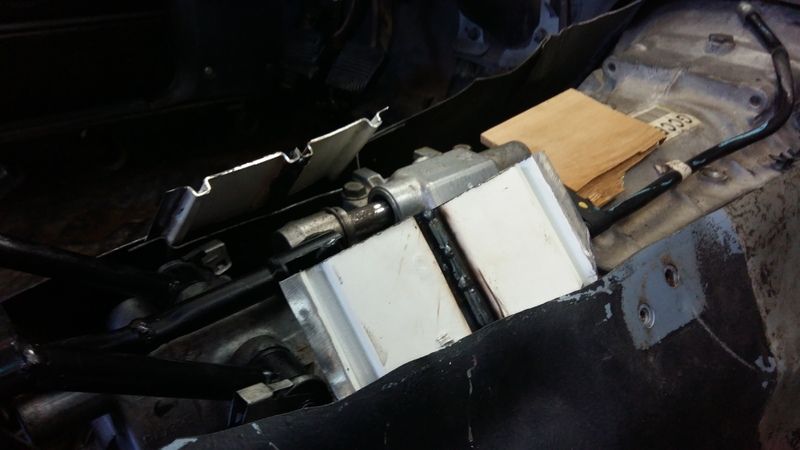
Funny how some weird scrap metal find a use you didn't expect. These are from some shelves I bought from Target when they pulled out from Canada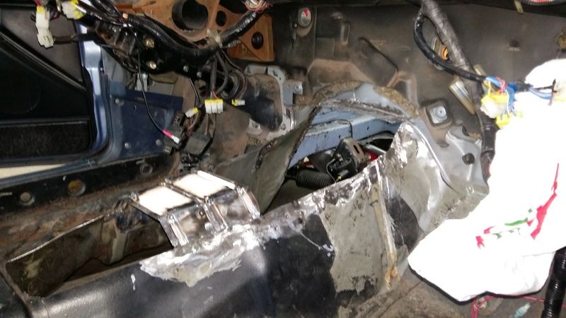
Frame completed
Then I made a template of the new steel out of cardboard.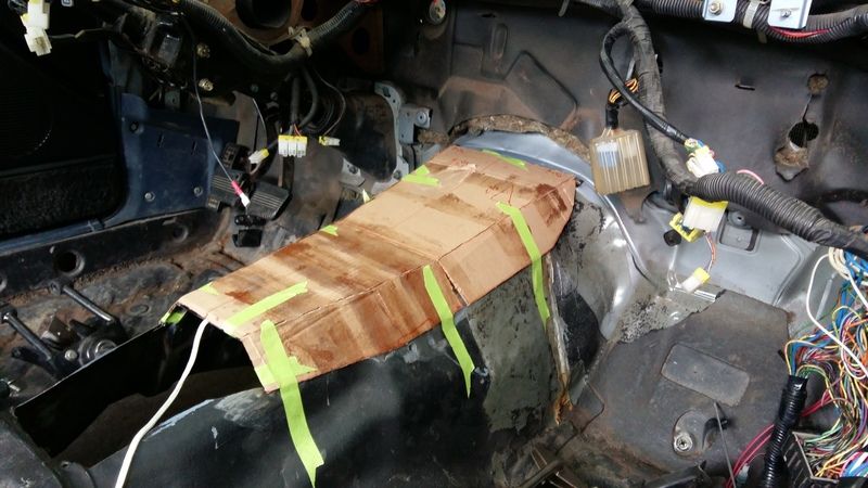
I then shaped some sheet metal to fit the tunnel. I used something slightly thicker than the floor panel an overlapped the floor pan on about 1''. Then I welded it from under and over to make sure the new tunnel is strong. I then applied some body panel sealer to protect it from rusting as well as making it look seamless.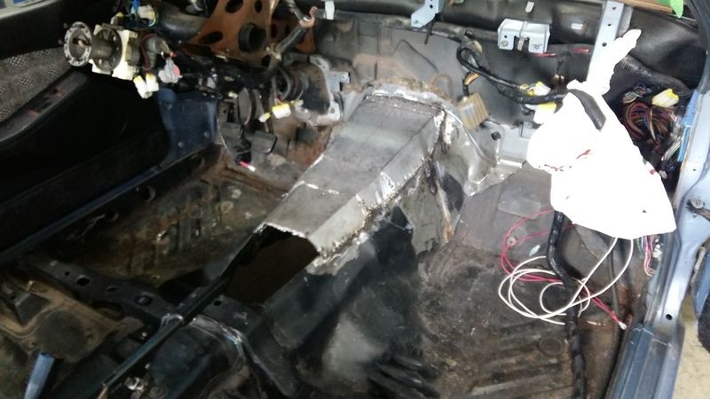
You have to be carefull when welding thin steel like this. The welding was made of 3 passes of 1/3 lenght bead to avoid distrortion.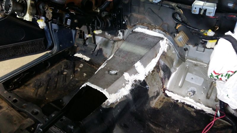
Seam sealed, I sealed a few other areas that I had repaired about 8 years ago too.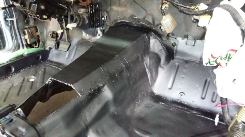
Painted new tunnel. Still obvious but clean looking. With the transmission under and the central console on top there isn't much way you could tell this work have been done.
So at that point, you have a LS swap that fit inside the car.
________________________________________________________________________________________________________________________________________
PART II: Other custom fitment needed
REVERSE SOLENOID:
The T56 have a device called a reverse solenoid. How it work is that under about 5mph, the ECM send a signal to that solenoid so it stop blocking you from going reverse. Without this it is possible to get into reverse by accident.
If you can still keep this functionning with your swap you don't have to worry about it really. If you can't (My GMPP ECM kit doesn't have this function), you have to find a way that suit you to feed 12V to this solenoid when you want to go into reverse.
Some people connect it to the brake switch, some other hide a switch somewhere. I did something a little bit more complicated. I bought a temporized relay circuit that I hid in the ash tray. Now that my audio deck is gone I made a custom switch panel with it. I have a switch that will feed that solenoid for 20seconds after I pressed it. This should allow me to do any reverse manoeuver and will keep the safety if I forget to take it off. I don't really want to get into reverse instead of 5th gear. 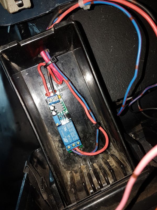
here's the circuit that is hidden in the ash tray.
Or if you really don't want to mess with it, it is still possible to go into reverse without sending 12V to the solenoid, it just requires more force to fight the spring loaded gate in the transmission. It isn't that bad honestly. I might just end up removing my circuit and drive it that way.
HEATER CORE:
Next issue you're going to face is the heater core port ending up right behind the right side head. If you don't care about keeping the heater core it's not a problem. I wanted to keep it.
So you will have to take the heater core out and make a new hole in the firewall for the ports about 4'' outward. Then extend the copper line on the heater core that same amount and find a longer hose for the lower port. Since you have the heater core in your hand, you should remove the lower ducting. It won't fit over the new bigger transmission tunnel anyway.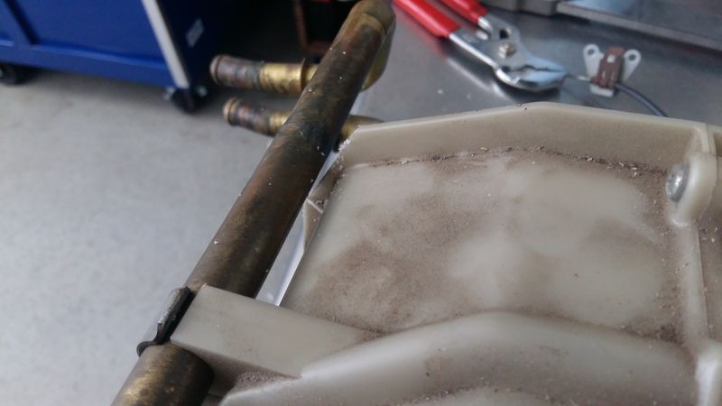
The top copper tube of the heater core have been extended by 4''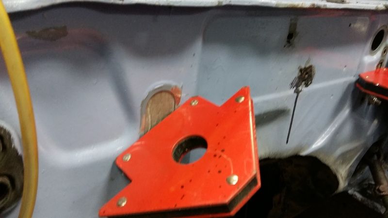
here you can see on the left the new port of the heater core sticking out. A blocking plate has been tacked to the firewall to fill the original hole.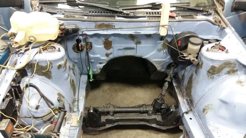
now it was time to fill some unused holes in the firewall and engine bay. I kept the throttle cable hole for the harness and deleted the speedo cable hole since you can't use one with the newer T56.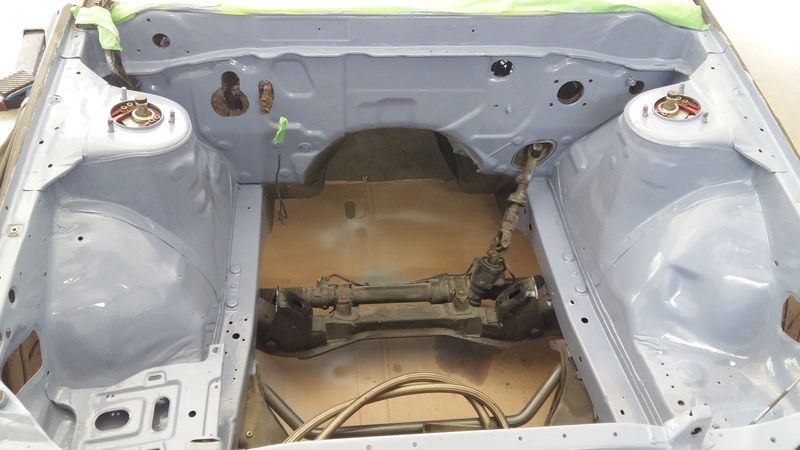
The result once sanded and painted.
Now just one last note on the heater core, from the reading I've done during the swap, the LS engines need to have a coolant flow through the heater core ports on the water pump in order to have the thermostat to function properly. Which mean you can either simply loop the ports together if you don't want to run the heater, or you have to provide a way of keeping the coolant flowing even when you set the heat control to cold. In our case, this shut a valve on the heater core and prevents that flow.
There are some LS swap heater bypass block that are sold for about 75$US but I decided to made my own since I had all the material needed at home ( an old pair of ski poles and a 2x3x4'' bloc of aluminium).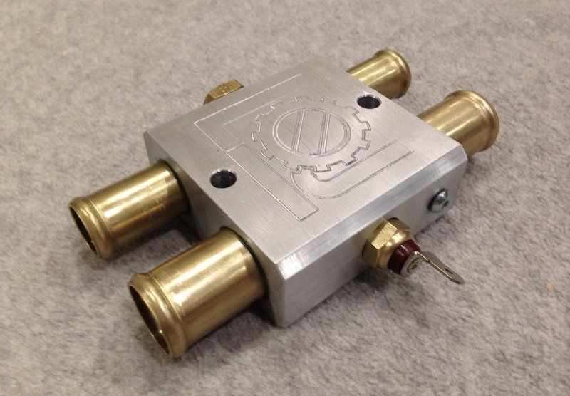
LOJkits sell a LS swap heater bypasse block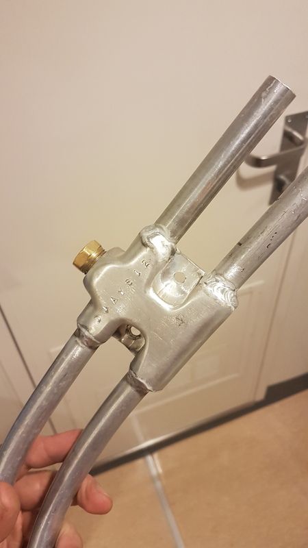
Here my house made bypass block. The tubes are longer to fit the hose I already adapted to the water pump ports.
HEADERS AND EXHAUST:
Now that part is a headache too. Iââ,¬â,,¢ll talk about what I had to do to fit my CXRacing headers. The fitment is probably different from other swap headers. I would still recommend to start from some S13 swap headers as these are probably be the closest to fit.
First issue would be the frame rail fitment. Our engine bay is slightly narrower than a S13. In my case the left side header contacted the frame rail and needed some massaging.
Now, why massaging the headers and not the frame? After watching this video (https://www.youtube.com/watch?v=azPKIjxmmdU) I figured out it was much easier to do this without any effect on the performance of the headers.
It also contacted one starter bolt on the right side (hammered the header there also) and slightly touched the steering column (same deal again).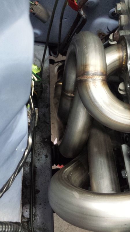
Right side header, there is plenty of room clearing the frame rail.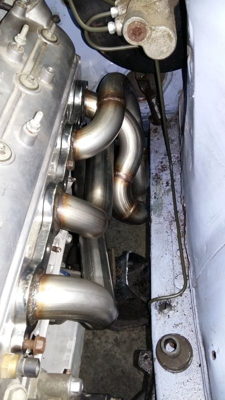
Left side header, you can see where it was hitting the frame rail. It have been hammered and now provide about 3/8'' of clearance.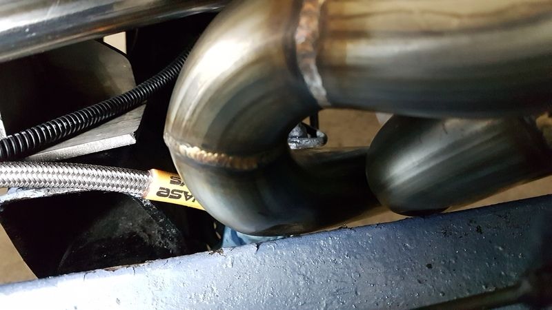
Once the header have been massaged enough, it finally clear the frame rail.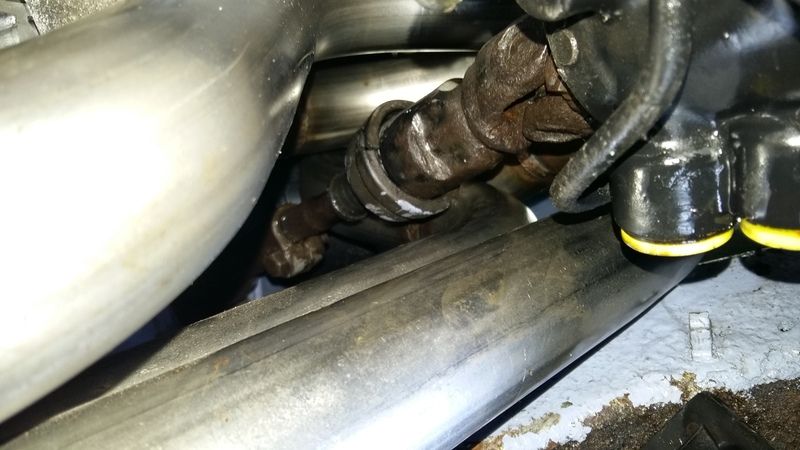
The steering column go right between the runners on the left side header. To install the header you need to remove the steering column, loosen the left side engine mount and lift the left side of the engine. Then you can slide the steering column inside the header and bolt it back.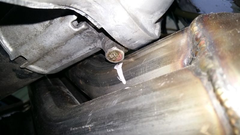
Here you can see the starter bolt that was touching the header
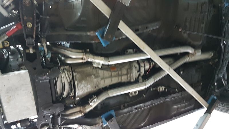
Next is the bottom of the headers that need to be modified. Again, just like the transmission, I didn't want anything hanging below the frame rails. The CXRacing headers exit in 3'', are too high and aim at our floor pan.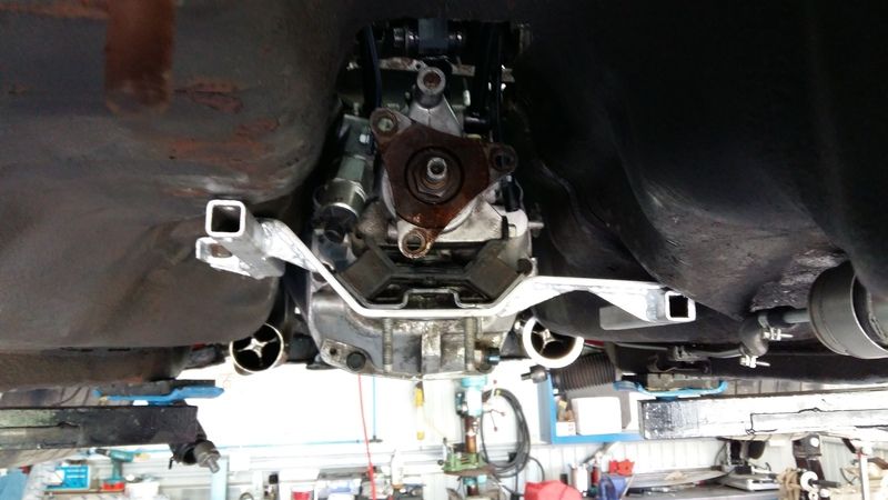
header exits aiming right at the floor pan.
So I bought some 3'' to 2 Ã,½'' conical reducers and chopped the header outlet. I then shaped the reducer on an angle to orient the exit below the floor pan. Reducing the diameter to 2 1/2'' made it easier to go around the T56 without going lower than the car already is.
There is not much room to spare around the big T56. Instead of using some V-clamp like the header used to had, I just made some straight exit. Some band clamps will take care of connecting the headers to the exhaust line.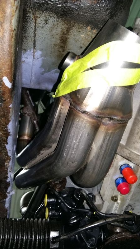
A glimpse of the conical reducer temporarily held by some masking tape
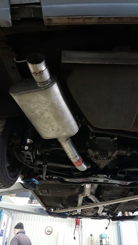
The tightest spot to fit the exhaust on the S12 IMO is where it goes above the rear subframe. Due to muffler choice and the space you have to pass the exhaust in there, I went with a Y pipe dual 2 ½'' to 3''. For a muffler, I only have a Dynomax VT which is supposed to be quiet like a stock muffler and open up a flap once you step on it.
Well for now I'll just say that this is still loud, and that was to be expected since there are no cats and no resonator in the exhaust line. I'll experiment with a side branch resonator to bring the noise down in the 1500-2500 rpm range.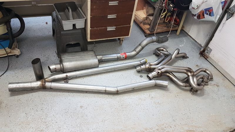
FUEL SYSTEM:
The fuel pump obviously needs to be upgraded. A walbro 255lph fuel pump is the minimum I would use with 400hp.
The main difference from other swaps is that the LS engine need a constant fuel pressure, not a vacuum referenced pressure like Nissan did at the time. Luckily this also mean a cleaner engine bay. The corvette already uses a fuel filter that integrates the pressure regulator. (WIX P/N 33737)
This filter will regulate the fuel pressure to 58psi.
Since there is now a header on the right side, I decided to install the filter/regulator under the floor. That way, there is only one fuel line going up in the engine compartment. There is a hump in the floor pan that make it fit nicely. I then added a metal shield to protect the filter from road debris.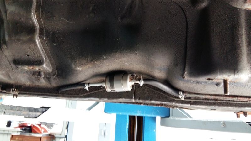
Fuel filter/regulator in it new location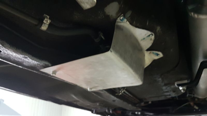
Fuel filter/regulator protected by a shield made of aluminium.
The fuel lines size has also been upgraded to match the fuel filter. I don't know if that was really a necessity but mine were starting to be rusty so I didn't take a chance.
OIL SYSTEM:
The oil filter on the LS engine screw onto the oil pan. I don't think any aftermarket oil pan have it setup that way. This mean that you have to run a remote filter. I placed mine next to the frame rail, under the battery tray. I already had thermostatic sandwitch plate and an engine oil cooler on my setup so your might be different.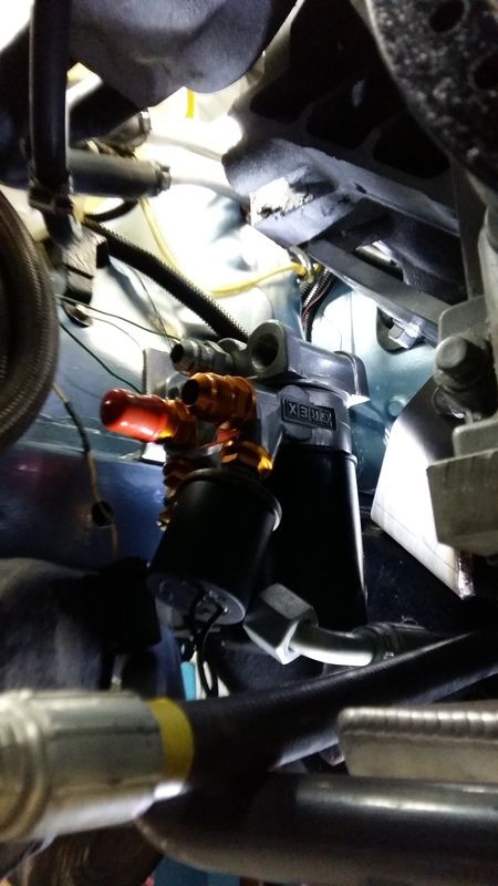
The oil filter, along with the factory CA20 oil pressure sender and a aftermarket oil temperature sender
DRIVESHAFT:
In my case this was a headache because of the CTS-V transmission. I contacted driveshaftshop with the measurement between the differential and transmission flanges and had a custom driveshaft made. The driveshaft in question is a 4'' aluminium with a CV on the transmission end. The CV will allow the driveshaft to plunge.
If you have a Camaro T56, all you can do is get a Camaro driveshaft, have it shortened with a 240SX Joint in the back and get it balanced.
CLUTCH:
This part of the swap goes just like any LS to S13 swap. I used a Sikky clutch master cylinder kit. This includes the line to the slave cylinder, a ¾'' wildwood master cylinder and an adapter plate to bolt it to the firewall.
I highly recommend buying a remote clutch bleeder kit. The slave cylinder in the T56 is shaped like a doughnut and is inside the bellhousing. The factory bleeder barely sticks out at about 2 clock on the bellhousing, making it almost impossible to reach. The remote bleeder is a must to be able to easily bleed the clutch.
If you have a CTS-V T56 like me and want a lighter flywheel (OEM is in the 40lbs range) you need to use a corvette C6 slave cylinder, which is higher. A lot of clutch setup need you to measure the gap between the slave and the pressure plate. I went with a kit on tickperformance.com (18lbs aluminium flywheel, monster stage 1 clutch and C6 slave) that do not need any shimming.
CLUSTER:
To run the OEM cluster, you will need to do some work to get the speedometer and the tachometer to work.
For the speedo, I called Abbott and had a Cable-X custom made with a spare speedo cable I have. In short, the Cable-X is a device that receives a VSS signal and then drives a small electric motor that will run a shortened speedo cable. I installed my Cable-X where the radio used to be. The Cable-X has a dozen dipswitches inside to change the conversion from the VSS to cable rotation. This way, you can adjust the speedo reading if you change the rear tire size or the differential ratio. The cable-X will take the signal directly from the vehicle speed sensor on the transmission and NOT the signal coming out from the ECM.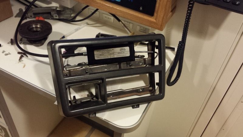
The cable-x fitted in the radio deck holder. The shortened speedo cable will simply loop inside the dash and go to the cluster.
For the tachometer, you will need to build a pull-up resistor circuit. This circuit is nothing really hard, it's just a resistance of about 1kOhm that raise the ECM tach signal to 12V when that pin on the ECM is floating. When the ECM ground the signal it will draw the 12V down near 0V. Once you have boosted this signal, you need to boost it again to simulate the voltage peak of the ignition coil discharging (the Tachometer is looking for pulses of 55V+). I tried to make my own signal booster from an automotive relay but it didn't worked. I ended up buying this signal booster from ebay that worked nice. There is to way of wiring it, you need to wire it for active low operation.
http://www.ebay.com/itm/TACHOMETER-SIGNAL-BOOSTER-SPARK-COIL-SIMULATOR-3-16V-Input-55V-Output-/142171581596
(If the link is dead, look for TACHOMETER SIGNAL BOOSTER / SPARK COIL SIMULATOR it is made by widget man)
ENGINE MANAGEMENT:
The ls serie engine pretty much come out of factory with a standalone system. The ECM is not looking for any inputs from another computer in the factory car. This makes the engine management easier to work with the swap.
If your engine/trans combo didn't come with the ECM, there is some stuff you need to know about your engine to make sure it will fit your engine.
Mainly:
-Is it a GEN III or GEN IV engine?
-Does it have a 24X or 48X crank reluctor
-Does it have a cable drive throttle or a DBW throttle (Drive By Wire)
Now I won't go in the details of which engine is what, google it and all the info will be right there to identify your engine. Mine is a GEN IV 48X crank reluctor with DBW. Luckily enough for my engine, GMPP sell a hot-rod engine controller kit that make the wiring job much easier and that won't be looking for the post catalyzer O2 sensor.
The ECM also controls the cooling fan, fuel pump, and come with a OBD2 port, and various output (Speedo, tach, MIL to mention a few).
POWER STEERING:
The LS pump flow much more than the Nissan one. You need to restrict that flow for the steering to feel right, other than that it will be over assisted.
Turn One make a restrictor for the LS power steering pumps with a hole sized for Nissan racks. This restrictor come out with a AN fitting.
The CTS-V pump also output a higher pressure than the Camaro and Nissan pump. 1700-1800 psi versus 1100-1200 psi for the Nissan and Camaro. For now I haven't done anything about it. The full pressure is only present if you are on the steering stop and trying to steer some more. This shouldn't happen if you are careful or in road racing application. If you plan to drift the car this is an issue.
The funny thing that I will look into is that the CTS-V pump is made by Toyota (Well, Toyoda, which is in the same group). It look very close to the 2003-2008 Toyota Corolla power steering pump. I still have to measure one at a junk yard and if it have the same dimension, get one and test what the output pressure is. This could be an easy way to lower the max pressure.I don't see the Corolla having as high of a pressure than the big heavy Cadillac. This part will have to be updated eventually.
I found the pump data on a toyota matrix FSM (same pump) and it pump the correct pressure for us (about 1100psi) so I say we are up to a good start with this.
CTS-V pump
Corolla pump
Jun 3, 2017, 2:08 pm · #1