Jan 6, 2006, 8:50 am · #1
A write up would be really helpful. I have a z31 Autopower rollcage that i\'m gonna modify and weld it in so I\'ll take a few pics also. I probably wont do it till feb but the write up would be a big help.
Browse › Tech ›Electrical and chassis
A write up would be really helpful. I have a z31 Autopower rollcage that i\'m gonna modify and weld it in so I\'ll take a few pics also. I probably wont do it till feb but the write up would be a big help.
Due to new regulations up here for the 06 drift season, the Toad\'s getting a spec cage installed.
I\'m having it designed by a (semi)famous (local) rally driver/rally shop owner.
I\'ll then bother Mr. Furious endlessly until we fab and install it.
I\'m trying to keep the passenger seat area intact, as well as most of the interior.
I\'ll get pics when we\'re doing it, and can add them to any thread on the subject.
I rarely have time to get online anymore (this week\'s been an exception) so it might be a while before anything makes it here.
hillkill what happened with the cage?
bump for interest
i wouldnt mind a write up either. DIY cages almost sound scary though :eek:
i wouldnt mind a write up either. DIY cages almost sound scary though :eek:
Well due to some problems (i.e. not bieng able to use the welder I was promised) the cage has been put on the back burner. I had all the tubing bent by chris alstons chassis works in sacramento. The main hoop is in already but a couple of parts were bent incorrectly. Then School started and I have had no time to work on her at all. But the good news is I finally saved up enough and bought my own welder. I plan on attending as many altamont events as I can once I get done with school and move back up to norcal.
Well due to some problems (i.e. not bieng able to use the welder I was promised) the cage has been put on the back burner. I had all the tubing bent by chris alstons chassis works in sacramento. The main hoop is in already but a couple of parts were bent incorrectly. Then School started and I have had no time to work on her at all. But the good news is I finally saved up enough and bought my own welder. I plan on attending as many altamont events as I can once I get done with school and move back up to norcal.
Dunno if anyone cares, but I'm going to use this thread, over time, to detail my Megasquirt adventures in my mk1 1985 Notchback ca20e.
If you don't know what it is, it's an aftermarket fully tunable (and inexpensive) fuel and ignition controller. You can read up on it here: http://www.megasquirt.info/
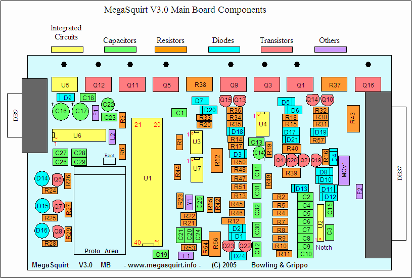
I'm going to run megasquirt'n'spark on the megasquirt 1 v3.0 pcb, so I can control spark.
I bought my megasquirt hardware at: http://www.diyautotune.com
Hardware mods:
wiring harness plugs removed from spare ca20e ecu.
ka24e throttle body (on its way from ebay)
Spare ca20e distributor with rpm & throttle advance disabled (on its way, bought from COandCA)
Cold air intake build out of intercooler piping with vacuum lines added. Throttle body outside diameter is 2.5", all my intake pipe is 2.5", and the pipe will end in a k&n universal filter (RC-9420).
Electric fan out of a civic.
25W 5 Ohm dropping resistors 825F5R0 — OHMITE — Wirewound Resistor
ACDELCO 15292 Accessory Drive Belt 88934275 (to remove fan pulley, unconfirmed fit) (Is the fan pulley connected to the water pump? I never did this one)
I spent the weekend reviewing the megasquirt manuals, and FSM. I have most of the wiring down (subject to experimentation/verification, don't blame me if you blow up your car, the ones marked with ? I am not completely sure of):
Stock CA20e pinout:
Looking at the back of the ECU where the harness plugs in, there are two plugs:
Left Plug:
115 114 ---- 113 112
111 X X 108 107
106 X X 103 102 101
Right Plug:
10 9 8 7 6 5 4 3 2 1
20 19 18 17 16 15 14 13 12 11
Pin, Color, Description
1) (P)  ??? Check Engine Light (Couldn't determine exactly what this is for)
2) (W)      Intake Air Temp
3) (Y/G)    Coolant Temp
4) (B)      O2 Sensor +
5) (B)      O2 Sensor GND
6) (Y/L)  ? Common wire for Intake Air Temp and MAF sensor (assumed to be +5V or +12V)
7) (LG/B) ? Provides signal/power to: Power Steering Oil Pressure Switch, Heater Fan, "Lightning Switch". I am not sure if this needs to be connected or not.
8) (G/Y)    Throttle Position Sensor switch: idle
9) (B/Y)    Start signal in to ECU (+12V when START in ignition switch)
10) (L/W)   Throttle Position Sensor swtich: full throttle
11) (G)     MAF #1
12) (G/R)   Throttle Position Sensor switch: Ecu output (assumed to be +5V or +12V)
13) (Y/R)   A/T Unit (I assume this means Automatic Transmission)
14) (G/OR)  Transmission Neutral Switch (GND when switch is on)
15) (L/Y)   MAF #2
16) (Y/R)   MAF #3
17) (G/R)   Distributor output signal (controls the twin/single spark system, and also modifies timing in the Auto Trans model)
18) (BR)    Check Connector (Not used)
19) (LG)    Check Connector (Not used)
20) (L)     Tachometer signal

101) (W/L)  Injector #4 GND/Signal
102) (B)    Ground
103) (B)    Ground
106) (B)    Fuel Pump GND/Signal (Should be connected to a relay! Megasquirt can't deal with the current on this wire)
107) (W/R)  Injector #1 GND/Signal
108) (B/W)  Injectors +
111) (Y/W)  Idle Up (turns on under high electrical load to stabilize idle)
112) (W)    Injector #2 GND/Signal
113) (Y)    Injector #3 GND/Signal
114) (L/R)  Air Regulator (Should be on when fuel pump is on, according to FSM)
115) (LG/B) EFI Relay switch signal

Got the kit today... damn there are a lot of components to solder! I sort of wish I bought one pre-assembled, I realize now that it may have been worth the extra $100 or so for a pre-assembled kit.
I think one more evening and it'll all be put together. I soldered together the MegaStim and the power & serial communications circuits on the main board today.
Also while I was at the auto parts store, I saw a universal cold air intake made by APC. It looks like I could get it to work with Megasquirt so long as the pipe isn't ridiculously big. It had pre-welded vacuum fittings, and maybe a bung, I can't tell... but all I need is one or two vacuum fittings and a place to drop my temperature sensor.
Is assembling the megasquirt very hard? I can't say I'm amazing at soldering or anything, but I have modded my share of video game systems.
i dont think id have the patience for that very intresting though and provides the driver almost complete control over his/her engine and thats cool
Smalltar_The_ImpalerIs assembling the megasquirt very hard? I can't say I'm amazing at soldering or anything, but I have modded my share of video game systems.
Have fun, man. I might pick one of those up, even just to assemble. I've been soldering for a few years now, I've always worked on electric guitars and amplifiers.
Holy crap... that's a lot of solder points, but I guess if you have the extra time and soldering equipment, nothing beats the smell of the 100 bucks saved.
Smalltar_The_ImpalerHoly crap... that's a lot of solder points, but I guess if you have the extra time and soldering equipment, nothing beats the smell of the 100 bucks saved.I love the smell of molten tin, anyways.
Yeah... so, I am rethinking soldering my own. I'm 3/4 through, and all the tests have passed so far, but it is far more time consuming than I had anticipated... I think I've spent 8 hours on it already.
The kit is simple, but I still made some mistakes in assembly that I had to fix.
Do yourself a favor and buy a pre-assembled kit if you get this thing!
I'll take your word for it and spend the extra hundred bucks when it's swappage time. As much as I love wasting time soldering, that's time that can be spent wiring.
Update:
I have the computer assembled for fuel-only right now, it bench tests with MegaTune and works with the Stimulator.
Because our cars have two sparks per cylinder, it'll be tricky getting the hardware to support the two coil outputs needed. I'm researching how to set the board up for that nonsense. I might have to get an MSD and just run one signal to that and have the MSD power the two coils, or figure out how to cram another coil transistor on to the board... (I don't think there's room for that)
Next step is to build the wiring harness and decide whether to use Megasquirt for ignition timing control.
I am waiting on a stupid clutch to come in the mail before I can even think of installing this stuff
Update:
I think I have all the wiring figured out. I labeled all my wires and am going to make a harness this weekend.
I'll post up a wiring diagram once I'm done (subject to modifications, as I haven't tried to start the car with it yet...)
Empedocles99Update:
I think I have all the wiring figured out. I labeled all my wires and am going to make a harness this weekend.
I'll post up a wiring diagram once I'm done (subject to modifications, as I haven't tried to start the car with it yet...)
jesus, thats alot of shit to solder...for that many point, id recommend going adn spending a bill on a weller.
Premojesus, thats alot of shit to solder...for that many point, id recommend going adn spending a bill on a weller.
Empedocles99Update: Fuel injection harness wired... megasquirt turns the fuel pump on, yay.
awesomeness. i think I might just order me a MSnS to assemble, because i have a whole lot of spare time, and spare time filled with smoke, molten tin, and electrical stuff is time well spent. then, one day, i'll try running it on Corsa or some piece like that.
Seraph1mawesomeness. i think I might just order me a MSnS to assemble, because i have a whole lot of spare time, and spare time filled with smoke, molten tin, and electrical stuff is time well spent. then, one day, i'll try running it on Corsa or some piece like that.
How much have u spent so far on the kit and components. And would u recommend get for someone doing a swap without a harness?
PowEr_oVeRHow much have u spent so far on the kit and components. And would u recommend get for someone doing a swap without a harness?
That isn't bad at all, I have another question though. The kit comes with a GM sensor for the air flow. Is that being used to replace the heavy MFS in the ca20?
PowEr_oVeRThat isn't bad at all, I have another question though. The kit comes with a GM sensor for the air flow. Is that being used to replace the heavy MFS in the ca20?
chris mate, you need to roll that beast on over sometime..i havent seen it in ages
Premochris mate, you need to roll that beast on over sometime..i havent seen it in ages
Empedocles99Well... hopefully the clutch is getting fixed today, finally! If all goes well, I can do it soon The lesson is that sport compact only takes forever to ship things.
COandCAdid you get the distrib? hey where did you get the ecu pinout for the mk1?? im doing a ka24de swap and i have been dead in the water without that pinout.
Empedocles99I got the distributor, I should have let you know. I JB Welded the weights so it won't advance now, yay.sweet dude. any chance you could put up a pic of the pinout? you can do it in my "it has begun" thread in tha ka24de section so i can stop hijacking your thread.
I used the two wiring diagrams in the factory service manual, the one in the ECS area and the wiring diagram in the back of the book.
As long as people don't abuse the downloads, I've got some s12 and s13 manuals on my website (see my sig)
This project is not dead... yet
Computer is wired.
Custom cold air intake made with all the vacuum lines installed.
All the sensors seem to be working, using the GM air intake temp sensor, and the stock nissan coolant temp sensor. MAP seems to respond when the engine is cranking, and the ka24e TPS works brilliantly, a direct fit.
Car cranks and starts, but dies right away. Need to figure out how to get it to idle now... I have to play with the 'after start' enrichment, and the fuel table.
I'll probably post pictures of the whole setup in a couple of days when I have some time.
This is exciting
Why have you spent $5000 and still have a CA20e? I would've swapped to a RB20DET or a CA18DET
eminem_rh25Why have you spent $5000 and still have a CA20e? I would've swapped to a RB20DET or a CA18DET
you will have no problem megasquirting a 18det after this man.
sam31183you will have no problem megasquirting a 18det after this man.
Got it to idle on the MS tonight, yay. It's tricky figuring out the initial settings, and trying to understand why the stupid thing refuses to idle, but I finally got it.
I'll post my tuned maps once I'm done
I would be keen to do this when your finished and have documented it. I have a mate running a MegaSquirt on his turbo'd 525i BMW and that makes over 200rwkw with just his 'laptop while driving' tune, and the motor hasnt even been opened yet.
How did you solve the twinspark problem?
Dave.I would be keen to do this when your finished and have documented it. I have a mate running a MegaSquirt on his turbo'd 525i BMW and that makes over 200rwkw with just his 'laptop while driving' tune, and the motor hasnt even been opened yet.
How did you solve the twinspark problem?
ca18det is my plan also, in about a years time. What controls the ignition atm?
Good luck with the rest of the project.
Empedocles99
I am running fuel only right now.
The twinspark problem is solved by having two ignition drivers on the megasquirt board, or by using an MSD, or a V8 coil driver.
The next steps for me are:
Tune
Ignition
Turbo
At any/some point this whole setup might be replaced by a ca18det though
sam31183I would have to say that the 18det will be on its way some time after you turbo the 20e....
Dave.ca18det is my plan also, in about a years time. What controls the ignition atm?
Good luck with the rest of the project.
Lots of work, finally got it running decently with the wideband
Drove it around town, it's pretty rich, have to tune and solve a bug here and there, but even un-tuned it is noticeably quicker and the rpms climb more smoothly.
I'm going to take it to the 1/8 mile drag strip tonight, might be able to tune a little after work, on the way to the track, we'll see what happens.
A more thorough writeup will be coming after I fix the bugs and get it tuned right.
Ohh hells yes, I ran the auto tuning software in MegaLogViewer on the data I collected yesterday. The car is noticeably faster now, especially between 5000->6500 rpms, it used to be pretty weak there, now it is much less weak.
Car's been running strong since. Still haven't bothered to tune the start up enrichments (it starts poorly when it's cold out). Many miles and probably 4 track sessions, no problems at all, it's dope.
Next is ca20et